| Extended name |
Unit | Column name |
Full description |
Picture |
| TIME |
| Date__(UT)__HR:MN |
TIME |
| Solar presence |
| Solar presence |
Time tag is followed by a blank, then a solar-presence symbol:
'*' Daylight (refracted solar upper-limb on or above apparent horizon)
'C' Civil twilight/dawn
'N' Nautical twilight/dawn
'A' Astronomical twilight/dawn
' ' Night OR geocentric ephemeris |
| Lunar presence |
| Lunar presence |
The solar-presence symbol is immediately followed by a lunar-presence symbol:
'm' Refracted upper-limb of Moon on or above apparent horizon
' ' Refracted upper-limb of Moon below apparent horizon OR geocentric ephemeris |
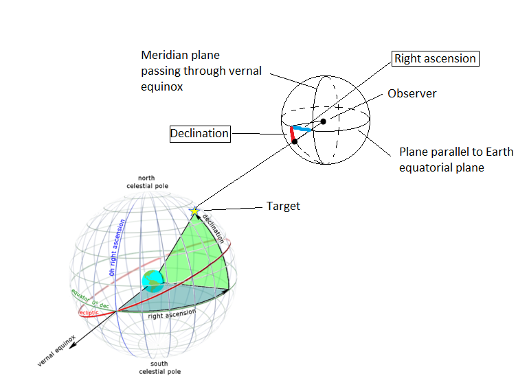
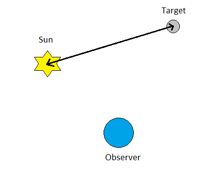
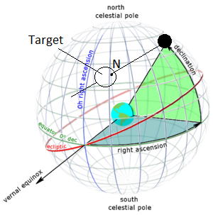
| 1. Astrometric RA and Dec |
HH MM SS.ffff | R.A._(ICRF/J2000.0) |
Astrometric(*) right ascension and declination of the target with respect
to the specified observing center/site, epressed with respect to the planetary ephemeris ICRF/J2000 equator and equinox (i.e. for equator and equinox calculated for date J2000).
Compensated for light travel time only.
(*) Not depending on features of body where observer is located.
|
|
| DEC_(ICRF/J2000.0) |
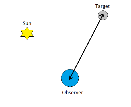
| *2. Apparent RA and Dec |
HH MM SS.ffff | R.A._(a-app) |
Airless apparent(*) right ascension and declination of the target center with respect to specified observing center/site.
Corrections and reference system vary depending on body where observing site is located:
- Earth:
- Reference system:
- Type: 3d/spherical
- Fundamental plane: Parallel to Earth equator for current date
- Center: Earth center
- Start point: Earth equinox for current date
- Corrections:
- light-time delay
- gravitational deflection of light
- stellar aberration
- atmospheric refraction
- precession
- nutation
- other motion of the spin-pole
- Body w/o rotational model:
- Reference system:
- ICRF/J2000
- Type: 3d/spherical
- Fundamental plane: Parallel to Sun equator, i.e. ecliptic
- Center: Sun center
- Start point: Earth equinox
- Corrections:
- light-time delay
- gravitational deflection of light
- stellar aberration
- (no atmospheric refraction)
- (no precession)
- (no nutation)
- Body with rotational model:
- Reference system:
- Type: 3d/spherical
- Fundamental plane: through equator of the body
- Center: Body center
- Start point: Earth equinox
- Corrections:
- light-time
- gravitational deflection of light
- stellar aberration
- (no atmospheric refraction)
- (usually no precession)
- (usually no nutation)
(*) Corrected as per above-lised quantities.
Reference 1
Reference 2
|
| DEC_(a-app) |
| 3. Rates; RA and Dec |
ARCSECONDS PER HOUR | dRA*cosD |
The rate of change of target center apparent RA and DEC (airless). d(RA)/dt is multiplied by the cosine of the declination.
Reference system:
- Type: 3d/spherical
- Fundamental plane: Parallel to Earth equator for current date
- Center: Earth center
- Start point: Earth equinox for current date
|
| d(DEC)/dt |
| *4. Apparent Az and Elev |
DEGREES | Azi_(a-app) |
Airless apparent azimuth and elevation of target center. Adjusted for light-time, the gravitational deflection of light,
stellar aberration, precession and nutation. Azimuth measured North(0) -> East(90) -> South(180) -> West(270) -> North (360). Elevation is with respect
to plane perpendicular to local zenith direction.
Topocentric only
|
 |
| Elev_(a-app) |
| 5. Rates; AZ and El |
ARCSECOND/MINUTE | dAZ*cosE |
The rate of change of target center apparent azimuth and elevation (airless). d(AZ)/dt is multiplied by the cosine of the
elevation angle.
Topocentric only
|
| d(ELV)/dt |
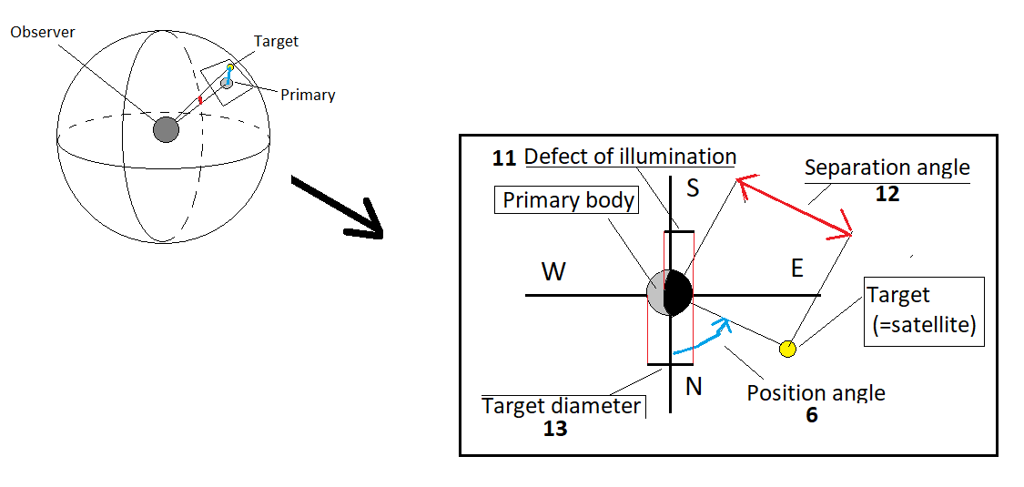
| 6. X & Y satellite coordinates & position angle |
ARCSECONDS |
X_(sat-prim) |
Satellite differential(*) X coordinate WRT the primary body.
X=[(RA_sat - RA_primary)*COS(DEC_primary)]
Non-Lunar satellites only.
(*)Differences between angles on the celestial sphere |
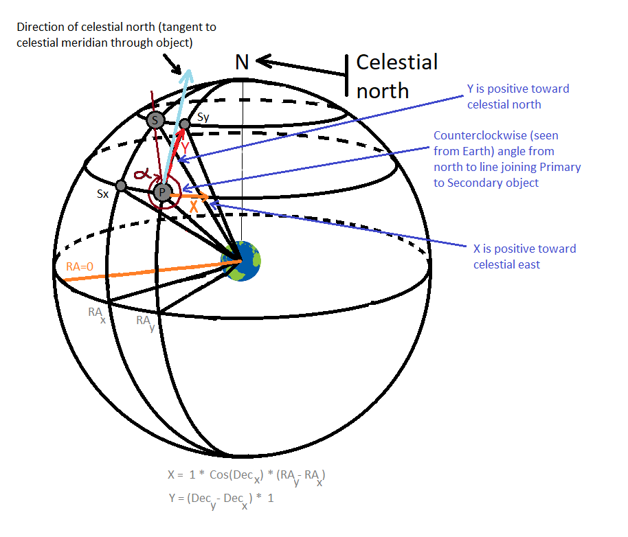
(Click for detailed explanation) |
| Y_(sat-prim) |
Satellite differential Y coordinate WRT the primary body.
Y=(DEC_sat-DEC_primary).
Non-Lunar satellites only.
(*)Differences between angles on the celestial sphere |
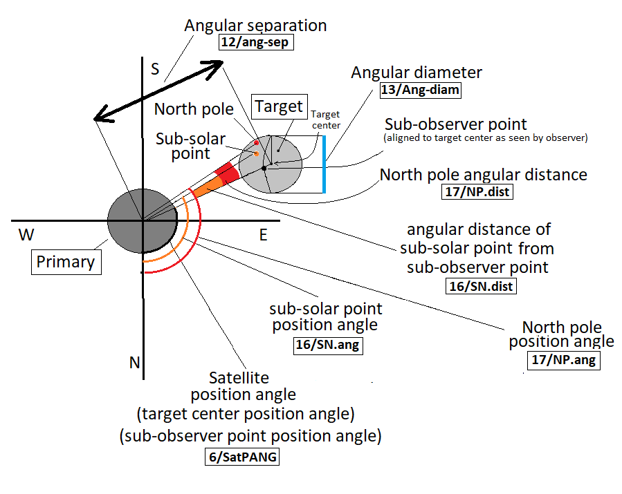
| SatPANG |
Satellite position angle in celestial sphere.
Angle start: line joining primary-body center to North Celestial Pole
Angle end: line joining primary-body center to target center (=satellite orbiting the primary body)
Direction: counter-clockwise (CCW, or east)
|
 |
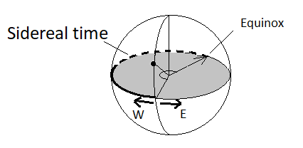
| 7. Local apparent sidereal time |
HH MM SS.ffff | L_Ap_Sid_Time |
Local Apparent Sidereal Time
Angle measured over the plane of "true-equator of-date" of the body.
Angle start: Meridian containing the observer on the center-body.
Angle end: meridian containing the true Earth equinox (defined by intersection of the true Earth equator
of date with the ecliptic of date).
Direction: Westward
Topocentric only.
|
 |
| 8. Airmass |
None (airmass) and magnitudes (extinction) | a-mass |
Available only for topocentric Earth sites when the target is above the horizon.
Relative optical airmass and visual magnitude extinction. Airmass is the ratio between the absolute optical airmass for the target's refracted CENTER point to the absolute optical airmass at zenith. Also output is the estimated visual magnitude extinction due to the atmosphere, as seen by the observer. |
| 9. Visible magnitude and surface brightness |
magnitudes |
mag_ex |
Target's approximate apparent visual magnitude & surface brightness. For planets and satellites, values are available only for
solar phase angles in the range generally visible from Earth. This is to avoid extrapolation of models beyond their valid (data-based) limits. |
| MAGNITUDE |
APmag |
| VISUAL MAGNITUDES PER SQUARE ARCSECOND |
S-brt |
| 10. Illuminated fraction |
PERCENT |
Illu% |
Fraction of target circular disk illuminated by Sun (phase), as seen by observer (=quantity 25). For value of phase angle see quantities 24 and 43 |
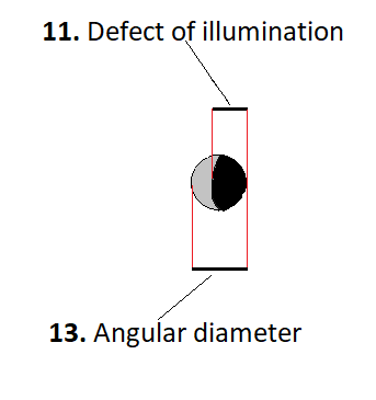
| 11. Defect of illumination |
ARCSECONDS | Def_illu |
Defect of illumination. Maximum angular width of target circular disk diameter not illuminated by the Sun. |
 |
| 12. Satellite angle separation/visibility |
ARCSECONDS | ang-sep |
Target-primary angular separation.
Angle start: line joining observer to target (satellite)
Angle end: line joining observer to primary body around which the satellite is orbiting
Direction: not used
|
 |
| Non-lunar natural satellite visibility codes (limb-to-limb) |
v |
Target visibility w.r.t its primary body (i.e. eclipses/occultations).
Possible values:
/t = Transitting primary body disk
/O = Occulted by primary body disk,
/p = Partial umbral eclipse
/P = Occulted partial umbral eclipse
/u = Total umbral eclipse
/U = Occulted total umbral eclipse,
/- = Target is the primary body
/* = None of above ("free and clear") |
 |
| 13. Target angular diam. |
ARCSECONDS | Ang-diam |
The equatorial angular width of the target body full disk, if it were fully visible to the observer. |
|
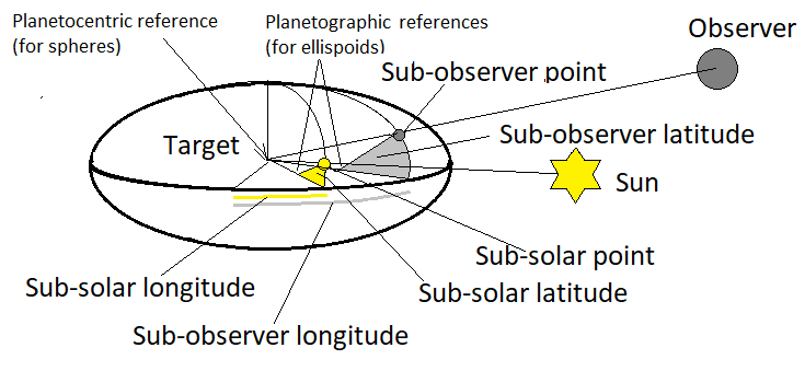
| 14. Observer sub-longitude and sub-latitude |
DEGREES | Ob-lon |
Apparent planetodetic longitude and latitude (IAU2009 model) of the center of the target disk seen by the observer
at print-time.
For a non-spherical target shape, this is not exactly the same as the "sub-observer" (nearest) point , but if not an
irregular body shape, it is generally very close. Down-leg light travel-time from target to observer is taken into account.
Latitude is the angle between the equatorial plane and the line perpendicular to the reference ellipsoid of the body. The reference ellipsoid
is an oblate spheroid with a single flatness coefficient in which the y-axis body radius is taken to be the same value as the x-axis radius.
For the gas giants Jupiter, Saturn, Uranus and Neptune, IAU2009 longitude is based on the "System III" prime meridian rotation angle of the magnetic
field. By contrast, pole direction (thus latitude) is relative to the body dynamical equator. There can be an offset between the magnetic pole and
the dynamical pole of rotation. Positive longitude is to the EAST. |
 |
| Ob-lat |
| 15. Sun sub-longitude and sub-latitude |
DEGREES | Sl-lon |
Apparent planetodetic longitude and latitude of the Sun (IAU2009) as seen by the observer at print-time.
For a non-spherical target shape, this is not exactly the same as the "sub-solar" (nearest) point , but if not an irregular body shape, it is generally very close. Light travel-time from Sun to target and from target to observer is taken into account.
Latitude is the angle between the equatorial plane and the line perpendicular to the reference ellipsoid of the body. The reference ellipsoid is an oblate spheroid with a single flatness coefficient in which the y-axis body radius is taken to be the same value as the x-axis radius. For the gas giants Jupiter, Saturn, Uranus and Neptune, IAU2009 longitude is based on the "System III" prime meridian rotation angle of the magnetic field. By contrast, pole direction (thus latitude) is relative to the body dynamical equator. There can be an offset between the magnetic pole and the dynamical pole of rotation. Positive longitude is to the EAST. |
| Sl-lat |
| 16. Sub Sun Position Angle and Distance |
DEGREES |
SN.ang |
Target sub-solar point position angle (CCW, or east, with respect to the direction of the true-of-date Celestial North Pole) |
|
| ARCSECONDS |
SN.dist |
Target sub-solar point angular distance from the sub-observer point (center of disk) at print time. Negative distance
indicates the sub-solar point is on the hemisphere hidden from the observer.
|
| 17. North Pole Position Angle and Distance |
DEGREES | NP.ang |
Target's North pole position angle (CCW, or east, with respect to direction of true-of-date Celestial North Pole)
at observation time. |
| ARCSECONDS |
NP.dist |
Target's North pole angular distance from the sub-observer point (center of disk) at observation time.
Negative distance indicates the planet's North pole is on the hidden hemisphere. |
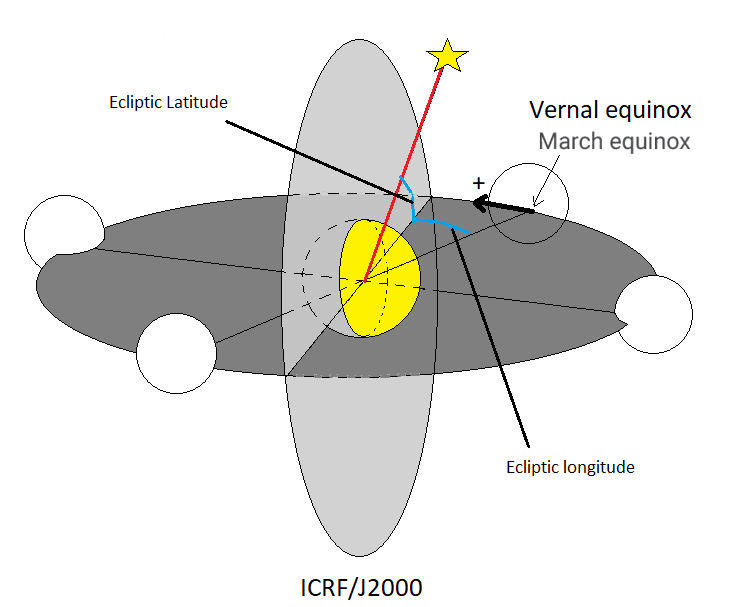
| 18. Helio eclip. longitude and latitude |
DEGREES | hEcl-Lon |
Geometric heliocentric J2000 ecliptic longitude and latitude of target center at the instant light leaves it to be observed at print time (print time minus 1-way light-time). |
 |
| hEcl-Lat |
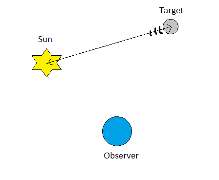
| 19. Helio range and rng rate |
AU | r |
Heliocentric range ("r", light-time-corrected) of the target center at the instant light seen by the observer at print-time would have left the target center (print-time minus down-leg light-time). The Sun-to-target distance traveled by a ray of light emanating from the center of the Sun that reaches the target center point at some instant and is recordable by the observer one down-leg light-time later at print-time. |
 |
| 20. Obsrv range and rng rate |
AU | delta |
Observer-centric range ("delta") of the target center at the instant light seen by the observer at print-time would have left the target center (print-time minus down-leg light-time); the target-to-observer distance traveled by a light ray emanating from the center of the target and recorded by the observer at print-time. |
 |
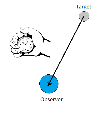
| 21. One-Way Light-Time |
MINUTES | 1-way_LT |
1-way down-leg light-time from target center to observer. The elapsed time since light (observed at print-time) would have left or reflected off a point at the center of the target. |
 |
| 22. Speed wrt Sun and observer |
KM/S |
VmagSn |
Heliocentric magnitude of target center velocity at the time light left the target center to be observed (print time minus 1-way light-time). These are absolute values of the velocity vectors (total speeds) and do not indicate direction of motion. |
 |
| VmagOb |
Observer-centric magnitude of target center velocity at the time light left the target center to be observed (print time minus 1-way light-time). These are absolute values of the velocity vectors (total speeds) and do not indicate direction of motion. |
 |
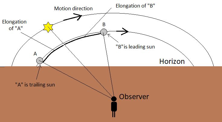
| 23. Sun-Observer-Target ELONG angle |
DEGREES | S-O-T |
Sun-Observer-Target angle; target's apparent SOLAR ELONGATION seen from the observer location at print-time.
The '/r' column indicates the target's apparent position relative to the Sun in the observer's sky, as described below:
- Observer on rotating body (considering its rotational sense):
- /T = target TRAILS Sun (evening sky; rises and sets AFTER Sun)
- /L = target LEADS Sun (morning sky; rises and sets BEFORE Sun)
- Observer on not rotating body (such as a spacecraft): the "leading" and "trailing" condition is defined by
the observer's heliocentric orbital motion: if continuing in the observer's current direction of heliocentric motion would encounter
the target's apparent longitude first, followed by the Sun's, the target LEADS the Sun as seen by the observer.
If the Sun's apparent longitude would be encountered first, followed by the target's, the target TRAILS the Sun.
NOTE: The S-O-T solar elongation angle is numerically the minimum separation angle of the Sun and target in the sky in any direction.
It does NOT indicate the amount of separation in the leading or trailing directions, which are defined in the equator of a spherical
coordinate system. |
 |
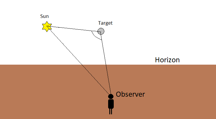
| 24. Sun-Target-Observer approximate PHASE angle |
DEGREES | S-T-O |
"S-T-O" is the Sun->Target->Observer angle; the interior vertex angle at target center formed by a vector to the apparent
center of the Sun at reflection time on the target and the apparent vector to the observer at print-time. Slightly different from
true PHASE ANGLE (requestable separately as quantity "43") at the few arcsecond level in that it includes stellar
aberration on the down-leg from target to observer. See also quantities 10 and 25 for illumination percentage. |
 |
| 25. Target-Observer-Moon/Illumination percentage |
DEGREES |
T-O-M |
Target-Observer-Moon (or Target-Observer-InterferingBody) apparent elongation angle, seen by the observer, between the target
body center and the center of a potential visually interfering body (such
as the Moon but, more generally, the largest body in the system except for
the one the observer is on).
A negative elongation angle
indicates the target center is behind the interfering body. The specific
interfering body for an observing site is given in the output header.
Labels:
T-O-M, Illu% (Earth observer, 'M' denoting "Moon")
T-O-I, Illu% (Non-Earth observer). |
 |
| % |
MN_Illu% |
Moon/Body illuminated percentage
Fraction of the Moon (or Interfering Body) disk that is illuminated by the Sun (=quantity 10).
|
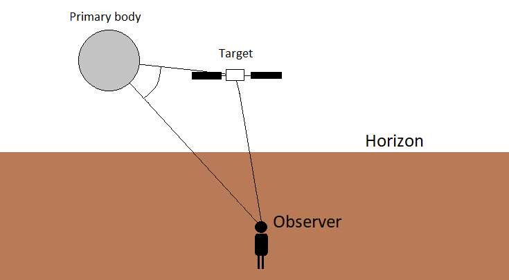
26. Observer-Primary-Target angle |
DEGREES | O-P-T |
Observer-Primary-Target angle; apparent angle between a target satellite, its primary's center and an observer, at observing location, at print time. |
 |
| 27. Radial and -vel posn.ang |
DEGREES |
PsAng |
The position angles of the extended Sun->target radius vector as seen in the observer's plane-of-sky, measured CCW (east) from reference frame North Celestial Pole. Primarily intended for ACTIVE COMETS, "PsAng" is an indicator of the comet's gas-tail orientation in the sky (being in the anti-sunward direction) |
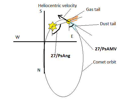 |
| PsAMV |
Negative of the target's heliocentric velocity vector, as seen in the observer's plane-of-sky, measured CCW (east) from reference frame North Celestial Pole. Primarily intended for ACTIVE COMETS, "PsAMV" is an indicator of dust-tail orientation. |
| 28. Orbit Plane Angle |
DEGREES | PlAng |
Angle between observer and target orbital plane, measured from center of target at the moment light seen at observation time leaves the target. Positive values indicate observer is above the object's orbital plane, in the direction of reference frame +z axis. |
 |
| 29. Constellation name |
text | Cnst |
Constellation ID; the 3-letter abbreviation for the name of the constellation containing the target center's astrometric position, as defined by IAU (1930) boundary delineation. See documentation for list of abbreviations. |
 |
| 30. Delta-T (TDB - UT) |
SECONDS | TDB-UT |
Difference between the uniform Barycentric Dynamical time-scale and the Earth-rotation dependent Universal Time. Prior to 1962, the difference is with respect to UT1 (TDB-UT1) and the 0.002 second maximum amplitude distinction between TT and TDB is not maintained. For 1962 and later, the difference is with respect to UTC (TDB-UTC) and periodic terms less than 1.e-6 second are ignored. Values beyond the next July or January 1st may change if a leap-second is later required by the IERS. Values from the present date forward through the next ~78 days are predictions; beyond that prediction interval, the last prediction is taken as a constant for all future dates. |
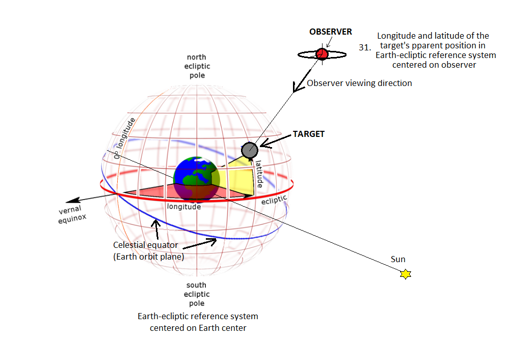
| *31. Observer ecliptic longitude and latitude |
DEGREES | ObsEcLon |
Observer-centered Earth ecliptic-of-date longitude and latitude of the target center's apparent position, adjusted for light-time, the gravitational deflection of light and stellar aberration. Although centered on the observer, the values are expressed relative to coordinate basis directions defined by the Earth's true equator-plane, equinox direction, and mean ecliptic plane at print time. |
 |
| ObsEcLat |
| 32. North pole RA and Dec |
DEGREES | N.Pole-RA |
ICRF/J2000.0 Right Ascension and Declination (IAU2009 rotation model) of target body's North Pole direction at the time light left the body to be observed at print time. |
 |
| N.Pole-DC |
| 33. Galactic latitude |
DEGREES | GlxLon |
Observer-centered Galactic System II (post WW II) longitude and latitude of the target center's apparent position. Adjusted for light-time, gravitational deflection of light, and stellar aberration. |
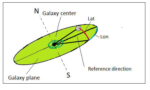 |
| GlxLat |
| 34. Local apparent SOLAR time |
HH MM SS.ffff | L_Ap_SOL_Time |
Topocentric only. Local Apparent SOLAR Time for observing site. This is the time indicated by a sundial. |
| 35. Earth -> site light-travel-time |
MINUTES | 399_ins_LT |
Instantaneous light-time of the station with respect to Earth center at print-time. The geometric (or "true") separation of site and Earth center, divided by the speed of light. |
| >36. RA and Dec uncertainty |
ARCSECONDS | RA_3sigma |
Uncertainty in Right-Ascension and Declination. Output values are the formal +/- 3 standard-deviations (sigmas) around nominal position. |
| DEC_3sigma |
| >37. POS error ellipse |
ARCSECONDS |
SMAA_3sig |
Plane-of-sky (POS) error ellipse data. These quantities summarize the target's 3-dimensional 3-standard-deviation formal uncertainty volume projected into a reference plane perpendicular to the observer's line-of-sight.
SMAA_3sig = Angular width of the 3-sigma error ellipse semi-major axis in POS. |
| ARCSECONDS |
SMIA_3sig |
Plane-of-sky (POS) error ellipse data. These quantities summarize the target's 3-dimensional 3-standard-deviation formal uncertainty volume projected into a reference plane perpendicular to the observer's line-of-sight.
SMIA_3sig = Angular width/ of the 3-sigma error ellipse semi-minor axis in POS. |
| DEGREES |
Theta |
Plane-of-sky (POS) error ellipse data. These quantities summarize the target's 3-dimensional 3-standard-deviation formal uncertainty volume projected into a reference plane perpendicular to the observer's line-of-sight.
Theta = Orientation angle of the error ellipse in POS; the clockwise angle from the direction of increasing RA to the semi-major axis of the error ellipse, in the direction of increasing DEC. |
| ARCSECONDS ^ 2 |
Area_3sig |
Plane-of-sky (POS) error ellipse data. These quantities summarize the target's 3-dimensional 3-standard-deviation formal uncertainty volume projected into a reference plane perpendicular to the observer's line-of-sight.
Area_3sig = Area of sky enclosed by the 3-sigma error ellipse. |
| >38. POS uncertainty (RSS) |
ARCSECONDS | POS_3sigma |
The Root-Sum-of-Squares (RSS) of the 3-standard deviation plane-of-sky error ellipse major and minor axes. This single pointing uncertainty number gives an angular distance (a circular radius) from the target's nominal position in the sky that encompasses the error-ellipse. |
| >39. Range and rng-rate sig. |
KM | RNG_3sigma |
Range +/- 3 standard-deviation formal uncertainty. |
| RNGRT_3sig |
| >40. Doppler/delay sigmas |
HERTZ | DOP_S_3sig |
Doppler radar uncertainties at S-band (2380 MHz) frequency |
| HERTZ |
DOP_X_3sig |
Doppler radar uncertainties at X-band (8560 MHz) frequency |
| SECONDS |
RT_delay_3sig |
Doppler radar round-trip (total) delay to first-order. |
| 41. True anomaly angle |
DEGREES | Tru_Anom |
Apparent true anomaly angle of the target's heliocentric orbit position; the angle in the target's instantaneous orbit plane from the orbital periapse direction to the target, measured positively in the direction of motion. The position of the target is taken to be at the moment light seen by the observer at print-time would have left the center of the object. That is, the heliocentric position of the target used to compute the true anomaly is one down-leg light-time prior to the print-time. |
| *42. Local apparent hour angle |
HH MM SS.fff | L_Ap_Hour_Ang |
Earth topocentric only Local apparent HOUR ANGLE of target at observing site. The angle between the observer's
meridian plane, containing Earth's axis of-date and local zenith direction, and a great circle passing through Earth's axis-of-date and
the target's direction, measured westward from the zenith meridian to target meridian along the equator. Negative values are angular times
UNTIL transit. Positive values are angular times SINCE transit. Exactly 24_hrs/360_degrees. |
| 43. PHASE angle and bisect |
DEGREES | phi |
"phi" is the true PHASE ANGLE at the observer's location at print time. See also 10, 24 and 25 |
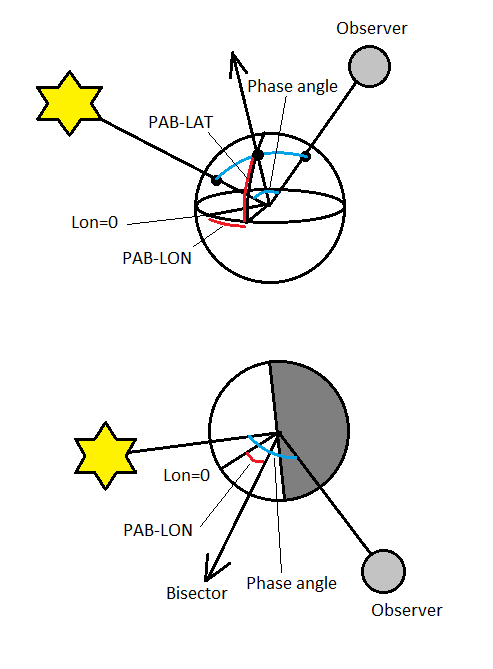 |
| PAB-LON |
J2000 ecliptic longitude of the
phase angle bisector direction; the outward directed angle bisecting the arc
created by the apparent vector from Sun to target center and the astrometric
vector from observer to target center. For an otherwise uniform ellipsoid, the
time when its long-axis is perpendicular to the PAB direction approximately
corresponds to lightcurve maximum (or maximum brightness) of the body. PAB is
discussed in Harris et al., Icarus 57, 251-258 (1984).
|
| PAB-LAT |
J2000 ecliptic latitude of the
phase angle bisector direction; the outward directed angle bisecting the arc
created by the apparent vector from Sun to target center and the astrometric
vector from observer to target center. For an otherwise uniform ellipsoid, the
time when its long-axis is perpendicular to the PAB direction approximately
corresponds to lightcurve maximum (or maximum brightness) of the body. PAB is
discussed in Harris et al., Icarus 57, 251-258 (1984).
|
Or select a pre-defined format below: